

A measurement tool used to measure various electrical values is called a multimeter.
Multimeters may test for continuity and measure voltage, current, and resistance.
Multimeters are incredibly useful tools for diagnosing a variety of electrical components. Although there are many potential uses, they are mainly used to test:
- Power cords
- Wall outlets
- Appliances
- Vehicle electrical systems
- Consumer electronics
Multimeters come in two varieties: analog and digital. Their displays are the primary distinction between the two. A moving needle over a graduated scale represents the measurements on analogue multimeters. The measurements are shown on an LCD screen in four or five numbers on digital multimeters. Another distinction is that while some analogue multimeters have a continuity feature, most do not.
WHAT IS A MULTIMETER
An essential measurement instrument in electronics is the multimeter. Voltmeter, ohmmeter, ammeter, and occasionally continuity are its three key components.
You can analyse your circuits' behaviour with a multimeter. The multimeter will assist you in troubleshooting when something in your circuit isn't working. You can use the multimeter in the following circumstances when working on electronics projects:
- The switch—is it on?
- Is this wire functioning properly, or is it damaged?
- What amount of current passes through this led?
- How much power do your batteries still have?
You can use this tool to find the answers to these and other questions.
A multimeter is a scientific tool that can check for various electrical problems. A system can be tested for either DC or AC voltage, open-circuit short-circuit amperage and issues. Also, you can do a continuity test to ensure the circuit routes are intact and continuous. As a result, this gadget may do the same task as a continuity tester.
A multimeter is a battery-operated gadget having two wire leads that plug into sockets on the device: one red and one black. Metal probes are attached to the leads' opposing ends. You can adjust the multimeter to the type of test you want to run using a dial or digital setting on the device's face.
One can check for continuity using the multimeter's ohm setting, which gauges an electrical path's resistance. In essence, a pathway's continuity increases with less resistance. For instance, the multimeter should register 0 or no resistance when the two wire leads are touched together (perfect continuity). On the other side, if the instrument displays infinite resistance, there is no pathway. When used in this fashion, the tool can inform you whether a device's connection has been established or whether it has been opened and is no longer effective.
BASIC UNITS OF ELECTRICITY A MULTIMETER CAN TEST
Due to the multimeter's capability to test for all three of the fundamental electrical units, including:
Voltage
- Using multimeters, you can test alternate (AC) and direct current (DC) voltages. Your home's electrical wiring uses AC voltage, whereas DC is largely used in cars, home solar energy systems, and consumer gadgets. Volts are used to measure voltage.
Resistance
- As measured in Ohms, resistance is the force that opposes the current flow across a circuit.
Current
- In general, current, measured in amps, is the quantity of electricity that flows through the circuit. The differential between the induced voltage and the resistance available determines how many amps pass through a circuit. The most typical unit of amps measured with a multimeter is milliamps (1/1,000 of an amp).
In addition to those three capabilities, some multimeters check for continuity or the lack of resistance inside a circuit. Dedicated continuity functions are not available on all multimeters, but those that do generate an audible beep once continuity is available. Testing the resistance should be done in the absence of this setting.
PARTS OF A MULTIMETER
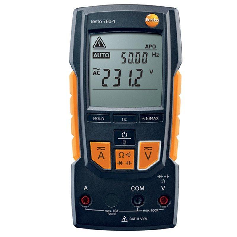
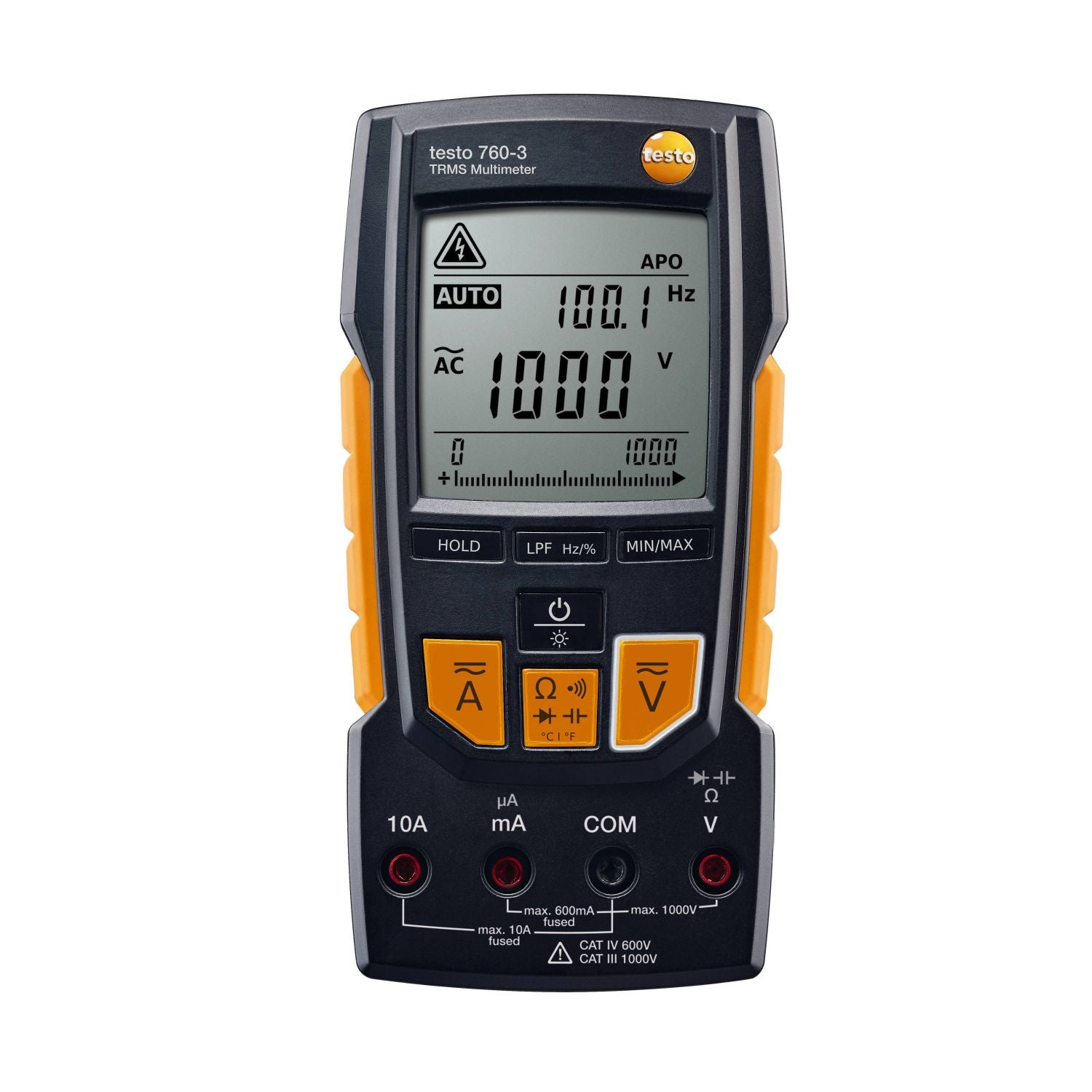
- Display: The window that displays electrical measurements.
- Selection Knob: A circular dial for choosing the kind of electrical unit to measure. You can choose between resistance (), amps (A), milliamps (mA), and AC volts (mA). A soundwave sign or a diode symbol (a triangle with a line on the right-hand side) is displayed on the selection knob to indicate continuity.
- Probes: The electrical component is physically tested using red and black cables. Each has a banana plug on one end and a sharp metal tip on the other. The banana plug links to one of the ports on the multimeter. Then, the metal tip probes the component being checked. The black cord is frequently used to check the ground and neutral (or common) connections, while the red wire is typically used for hot terminals, even though there is no real difference between the two probes.
- Ports: Three ports are typically found on multimeters: COM (or "-"), mAV, and 10A. The common connector, or COM, is where the black probe is often hooked. The red probe is plugged into the mAV port to monitor voltage, resistance, and current. When monitoring currents greater than 200 mA, the 10A port is specialised. One V setting for resistance and volts and one AmA setting for current are available on some multimeters' four ports, which divide the mAV setting's functions into two.
HOW TO USE A MULTIMETER
Measuring Volts
Whatever you're testing, set the selection knob to either AC or DC volts. Put the red probe on the component's positive terminal and the black probe on the component's negative terminal.
Consider testing a typical, 3-pronged electrical socket in a US home as an illustration. Ensure the probes are inserted into the correct port before setting the selection knob to AC volts. Put the red probe in the upper right slot and the black probe in the neutral space at the top left of the output (hot). If the testing doesn't show 120 volts, there may be a wiring problem. If you insert the red prong into the neutral slot and the black one to the u-shaped slot on the outlet's bottom (ground), and the measurement is higher than 0, it's another sign that the wiring needs professional checking.
You can also check the device's ground by placing the red probe in the hot slot and the black prong in the bottom slot of the outlet. The outlet has a poor base if the measurement is below 120 volts.
Checking Continuity
Turn the selection knob to continuity if your multimeter has a dedicated continuity setting. Touch the probe tips together to ensure the metre and probes are functional. If it's functioning properly, it should beep.
Checking the operation of a power cord is frequent use of continuity testing. Start by placing a multimeter probe against one of the male sides of the power cord's prongs. The other probe should be inserted into the matching slot on the cord's female end. If there is continuity, the multimeter will beep audibly. To the remaining male prong and female slot, repeat this procedure. The power cord has to be changed if there is no beeping on either side.
Next, connect one of the probes to a male prong on the cord's male end and the other probe to a male prong on the same end. A short means the cable needs to be changed if the metre beeps.
You can test the resistance if your metre doesn't have a continuity setting. Use the same process before and set the selection knob to the position. The main distinction is that now, rather than listening for an audible beep, you're searching for reading on display between 0 and 1. The circuit lacks continuity if the readout is one or OL (open loop), and the cord needs to be changed.
How is continuity achieved?
If there is only a very small amount of resistance—less than a few ohms—between two locations, the two spots are electrically connected, and you will hear a continuous sound.
If the sound is intermittent or nonexistent, it indicates that the component under test has a bad connection or isn't attached.
Warning: Make sure to power off the system before testing continuity! Disconnect the power source!
Measuring Resistance
When examining the resistors in an electrical component, measuring resistance is frequently performed in addition to continuity testing (like in a speaker).
Find the resistor's electrical resistance if you're checking it. The owner's manual for the component being checked or a label on the resistor should contain this information. Place each probe of the multimeter on a lead of a resistor. Then, set the selection knob to the preset. The resistance value shown on the meter's display should match the resistor's rating if the resistor is operating properly. If not, the resistor has to be replaced because it is broken.
Measuring Amps
As an illustration, measuring amps is one of the most popular applications for diagnosing vehicle electrical problems, a parasitic draw on the battery.
DIGITAL MULTIMETER SAFETY
When performing electrical measurements, each application for a digital multimeter poses potential safety risks that you must consider. Before using any electrical test equipment, people should always read the user's manual to learn the right operating techniques, safety measures, and limitations.
CHOOSING A MULTIMETER
A large range of multimeters with various features and accuracy are available. Voltage, current, and resistance—the three simplest but most important numbers in your circuit—are measured using a basic multimeter, which costs approximately $5.
This multimeter won't last very long and isn't particularly accurate, as you can probably predict. Depending on what you plan to perform, whether you're a novice or experienced electrician, and your budget, the ideal multimeter for you will vary.
BUY QUALITY HVAC MULTIMETER FROM HVAC SHOP
Every electronics lab needs a multimeter as a basic piece of equipment. This beginner's guide provides instructions on how to use a multimeter. You've mastered the techniques for measuring voltage, current, resistance, and continuity.
HVAC Shop offers analogue and digital multimeters for HVAC professionals and DIYers. Check out trusted brands to find the best tool for you and your business.